|
| This page describes how one can install the bimmerworld.com cooling kit for the front brakes of the E46M3. The bimmerworld kit is comprised of backing plates, flanges, silicon hoses and all necessary mounting hardware. NOTE: sometimes the 3" aluminum tube and long bolt are omitted. Also, some optional parts should be considered too, particularly silicon hose from a local vendor. You'll need about 7-8 feet. The Bimmerworld hose is very stiff and most race shops will carry a couple of brands. FreyRacing.com carries a black silicon hose thats pretty flexible but strong, about $48 for 10'. |
|
| Only minor tools are needed such as an 8mm socket, screwdrivers, box-knife, jigsaw, and dremel tool and/or files. The only unusual tool is a 3" diameter hole saw-type bit to cut holes into the stock passenger-side brake duct and the undertray (from Home Depot or equivalent). 9" Tie-wraps are useful for suspending the brake caliper and securing the hose. Some 1" fender washers with 1/4" holes are useful to securely mount the flanges and spread any twisting forces to a larger surface area. |
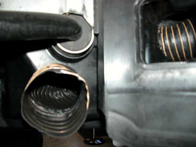
| NEW detail on extra parts used: At left is the collecting duct ($25) from FreyRacing.com. Its used to force all the air on the passenger's side into the hose. It also centers the hose. On the right is the simple rain gutter adapter used as a connecting tube for the outboard hose segments. Details below. |
| Plastic rain gutter mesh to prevent debris in both ducts: From OrchardSupply Hardware or HomeDepot, you can get plastic black mesh to block debris like big insects or leaves from getting into your rotors. Details below. |
I did the duct & hose work in 2 sessions in about 4 hrs; but with these instructions & photos, it should take less than 2 hrs. Update: I helped dougkm install his cooling kit and we finished in 2.5 hrs but this included R&R'ing his Brembo rotors & pads.
1. Preliminaries. Loosen the lug bolts of the front wheels, jack the front end of the car up and support the car at the 2 front jack stand positions. The front end can be jacked up by the central pad behind the oil drainage plug cover. Once on jack-stands, remove the wheels.
2. Accessing the passenger-side duct. The fender liner is in 2 parts; the lower front
part detaches and reveals the brake duct. Everything is held by 8mm hex-head screws but there is one
plastic retainer which has a phillips head. Remove the 8mm screws that hold
the lower section of the fender liner. Also, loosen the closest 8mm screw
in the upper fender liner section (helps reassembly).
Remove the lower fender liner. Note that part of the liner is held by an
overlapping metal edge
3. Remove the passenger-side duct. There are 2 plastic retainers (collar with pin) that attach the duct to a metal bracket. With a narrow flat-blade screwdriver, apply pressure to the back-side of the pin. You want to loosen the pin so the flat head is free to grab with your fingers. You could also try to grab the flat, top part of the pin with a needle-nose pliers but this will mess the pin up. Its better to work it loose from the back side.
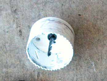
4. Cut a 3" hole into the passenger-side (PhotoP1): I bought a 3" diameter hole saw-type bit from Home Depot. This has a drill bit in the center to get it started. The plastic is very soft and will present no problems. You could drill a pilot hole for perfect positioning. I used a jigsaw to enlarge the circular hole into an oval, about 5" wide. A dremel tool can be used to round off the edges.
5. Remove the undertray. The undertray is held by 7 8mm screws, 2 along each side and 3 at the back. Slide the tray out. You may want to clean the tray of any residual cosmoline. I used a 70% solution of isopropanol, Goof-off works too.
6. Holes in the undertray. Cut 3" holes into the undertray (Photo P6, P7 & P8). You want to cut a hole between the curve for the swaybar bushing and the steering rod. The plastic is not flat here so you want to drill a pilot hole. Round off the edges with a dremel tool and/or file. The hole should be slightly larger than 3" to allow for hose movement.
Addendum: JW's new Bimmerworld kit had revised flanges which have minimally-sized attachment tabs. For his installation, JW cut the holes in the undertray using the 3" hole saw so that the two bolt holes on the flange tabs are over the flat surface of the undertray. After cutting, the 3" diameter holes will need to be enlarged with a Dremel tool to accommodate the added diameter of the hose and the clamp.
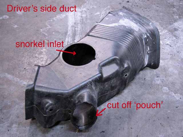
7. Driver's side duct. Cut off the end of the driver-side duct 'pouch' (PhotoP3). This
can be done without removing the driver's side duct, but you can remove the
driver's side duct in a manner similar to the method for removing the passenger's side duct
with 2 exceptions. There are two gizmo's attached to the corner cover on the
driver's side. The 1" diameter gizmo pops out with 4 small tabs.
The other one is a 1" long, thin probe with a difficult to remove wire harness.
Once detached, I leave this corner cover suspended with a tye-wrap to relieve strain
on the wire.
Examine the driver's-side duct. There is the rectangular hole at the back and
a hole at the top which feeds air into the intake ('snorkel' shown in PhotoP3). To
the left (when viewed from the front), there is a 'diverticulum'
or pouch. It goes nowhere and its' rounded-end can be cut-off. My
guess is that BMW designed the 'pouch' to create turbulence and
high pressure to promote air getting sucked into the snorkel.
To cut the 'pouch' off without removing the driver's side lower
fender liner or duct, use a box knife to cut along the lower edges. A dremel tool
with a cutting blade was used to cut across the middle. This gave me access
to cut the upper part from the inside of the pouch.
Addendum: For JW's installation, instead of cutting the 'pouch', he cut a large hole to insert the entire diameter of the hose into the duct. This was because having the hose clamped to the inside of the flange would make it difficult to put the duct & undertray back on the car as a unit. Caution: make the amount of hose that is inserted into the duct short enough to prevent obstructing airflow into the vertical engine air intake (but long enough so the hose stays in the duct).
8. Re-install the passenger-side duct. Align the duct's mounting holes with the metal bracket's holes. Insert the pin collar first into the hole in the bracket and then insert the central pin.
9. Insert the silicone hose. About 2.4 feet are required for the
passenger's side. Flatten one end slightly and insert it from the
front, then from beneath the car, pull on the hose gently. I used
a tie-wrap to secure the hose. For the driver's side, about 18" of
hose are needed (longer if you install the flanges and stick the
hose into the driver's side duct). Attach a 3" hose clamp around the slightly flattened
end of the hose and attach it to the cut end of the driver's side
duct. I applied a 1" wide section of duct tape to the duct to provide
friction which helped the hose not wiggle when i tightened the clamp's
screw. Secure the hose with a tie-strap. See Photos P2 & P4.
A collecting duct for the for the hose on passenger's side duct can
be installed to force all the air entering this duct into the hose.
See photo P11.
10. Re-attach the undertray. Insert the forward end of the tray into the bumper lip, while propping it up with your knees, insert the hose thru the cut holes of the tray. Secure the tray and attach the screws. You will probably have to tug on the hose to remove any slack.
Addendum: For those with flanges installed, attach the hose to the internal side of the flange (secured to the undertray). Push, pull & tug the hose from both ends to get the hose into position in each of the brake ducts. This does take some patience.
11. Accessing the stock dustshield. Loosen the 16mm bolts that attach the caliper carrier. Don't let the caliper hang, but suspend it with a wire, tie-wraps or place it on a box.
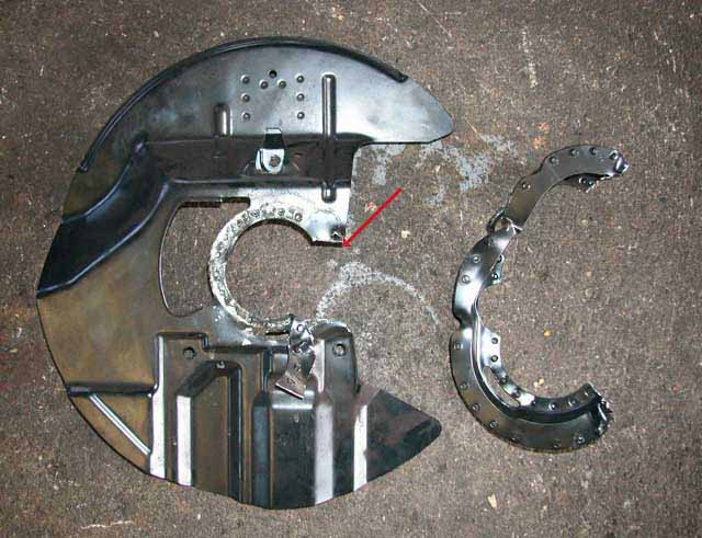
12. Remove the stock dustshield.
The dust shield looks roughly like a broad-brimmed hat.
It consists of a cylindrical collar section connected to a
'flat' brim. Remove the 3 attachment bolts.
With a large flat screwdriver, split the flat section away from
the 'brim' section. The metal is very soft. After separation,
you can cut the flat section with tin-snips across the narrowest
section. Subsequently, with the tin-snips, cut across the
cylindrical section. This takes a little more effort because of a lip.
See photos P13-P15.
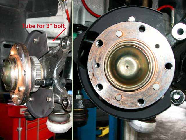
13. Install the backing plate. The top attachment point requires the 3" bolt and a 3" aluminum tube. I had to shorten the tube by 2-3 mm to prevent rubbing of the rotor on the backing plate. A couple of extra washers offset the bolt enough to enable a tight fit into the mounting hole. A few drops of blue loctite were used for all 3 attachment bolts.
14. Installation of custom flanges. If you have the flanges, align the custom flanges to the detached undertray. Drill mounting holes into each side of the undertray adjacent to the 3" diameter hole cut for the hose. Attach the flanges to the undertray. I have some 1" diameter fender bushings that can be used on the backside of 2 of the 3 attachment holes. This should reduce twisting forces on the undertray mounting points by spreading the load as the hose shifts during extreme wheel movements.
15. Assembly of internal & external hose sections.. You will need an extra pair of hands for this step. Slip 3" hose clamps around the ends of the internal hoses already attached to the ducts. Slip the undertray into the front bumper, hold it in position while If you don't have the flanges, just push the hose through the hole in the undertray.
Addendum: If you have the flanges, the assembly of hoses to the undertray and ducts is reversed from above. Attach the hose sections to the flanges secured to the undertray and push, pull & tug the hose into the brake ducts.
Position
the undertray to attach the seven 8mm mounting screws.
Now that the undertray is attached with internal hoses connected,
attach the external hose sections from the backing plates to the
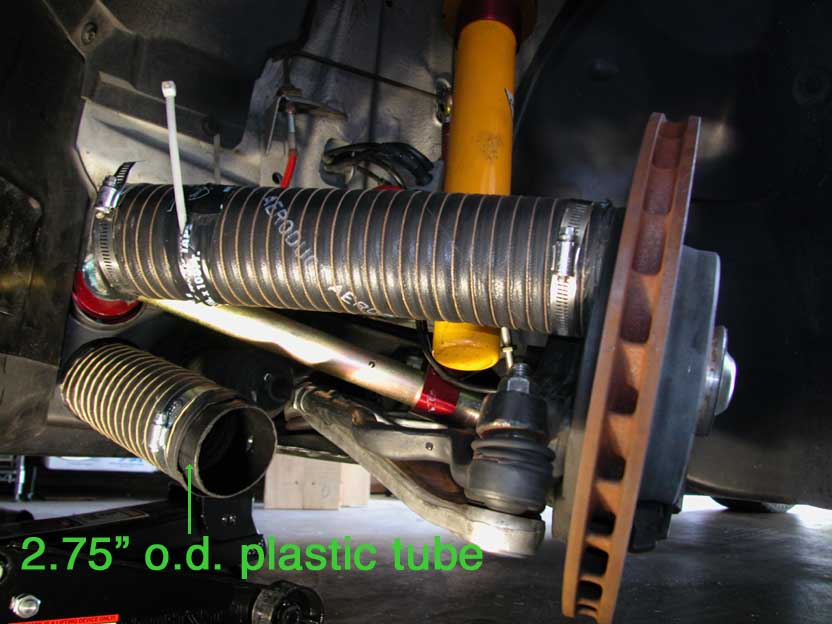
external part of the flange (if you have them). If you don't have
the flanges, see pix P16 & P17 where I used a 2.75" outer diameter
plastic tube to join the inner & outer hose sections. Use 3" hose clamps
to secure the hose to the flanges or tube. After 14 driving events,
there has been no appreciable wear on the hose from the plastic
edges of the undertray hole...but this is a possible maintenance
issue, which is avoided by the metal flanges. Even though I have
the flanges, i'm not installing till i see a problem with the
current setup; e.g. a rip or hole in the hose could arise from
chafing against the edge of the hole- but the hose fabric is
pretty stiff and i could always reinforce it with duct tape.
| P1. Modified passenger's side duct cut with oval hole viewed from the side which is mounted to rectangular metal bracket (see next pix). |
|
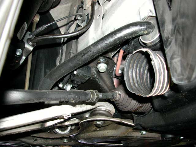
| P2. Passenger's side duct with hose inserted from the front of the duct. The hose has to be slightly flattened to pass thru the hole. Viewed from floor looking up. |
|
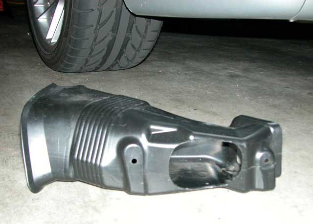
P3. Driver's side duct cut in situ. The driver's side duct has an 'outpouch' that ends in an oval. That end can be cut with a box knife & dremel tool without removing the duct. After cutting, a hose can be clamped onto the remaining 'oval-cylinder'. Top: Here's the driver's side duct after removal and slicing the 'pouch' off. Its easier to slice the 'pouch' off when the duct is removed, but its a little more effort to remove the driver's duct. Bottom: Viewed from floor looking straight up Addendum: If you have the flanges installed, remove the driver's side duct and just cut off the 'pouch' with a jigsaw or Dremel tool with cutting blade, leaving a 3" hole in which you will insert the hose. Be sure to not obstruct the snorkel thats also in the driver's side duct (See PhotoP5). |
|
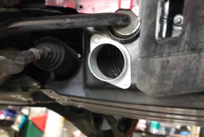
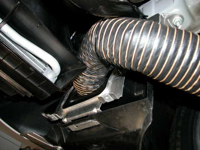
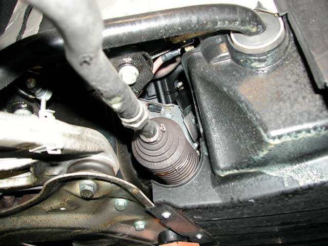
| P4. Driver's side hose attached to cut duct. |
|
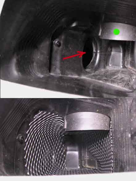
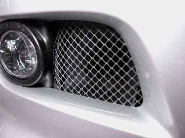
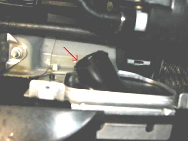
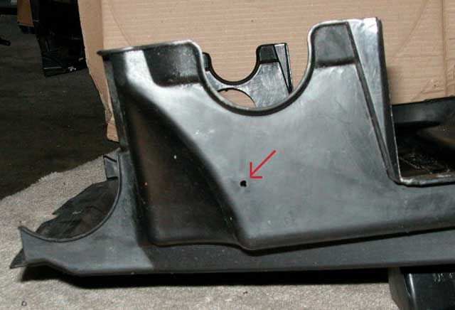
| P5. Front view of driver's side duct. Top: Red arrow shows the front of the 'pouch'. Green dot is the 'snorkel' or vertical engine air intake pipe. Bottom: Driver's side duct with some black plastic rain gutter mesh to prevent debris from getting into your rotors. The mesh can be obtained from HomeDepot or OrchardSupply Hardware. The mesh is about 6" wide and 12" long and just wedged into place. Its too large to be sucked into the snorkel or pouch. |
|
| P6. Exterior view of the unmodified tray. Passenger's side view. |
|
| P7. Position of guide hole before cutting with 3" hole bit. |
|
| P8. Exterior view of hole in attached tray. Note the passenger-side duct at the right. This photo is only for illustrative purposes. You would not install the undertray without snaking the hose through the ducts and then through the undertray! |
|
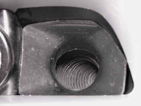
| P9. After installing the fender liner, a view of the silicone hose installed through the 3" hole in the tray, passenger side |
|
| P9.1 Addendum: JW's installed flanges. Note the restyled flanges and position of the mounting tabs on the flat part of the undertray. |
|
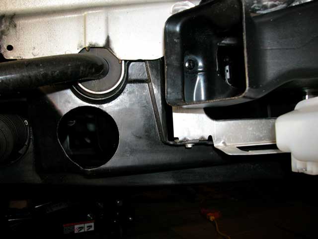
| P10. Another view of the installed hose. Note: thru the stock rectangular hole of the factory duct, one can see the hose exiting the duct through the oval hole and entering the space above the undertray. |
|
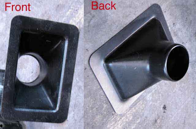
| P11. A view of the passenger's-side duct with collecting duct. Top:
The collecting duct was purchased from FreyRacing.com. It has a 3" diameter tube at the back.
The edges need to be trimmed to fit into the factory brake duct; in particular, one of the corners needs to be
trimmed off, in addition all of the rectangular edge. Middle: Installed duct in passenger's side factory brake duct. A hose clamp attaches the hose to the duct. Bottom: Black plastic mesh in passenger's side to prevent debris. Just trim to fit. |
|
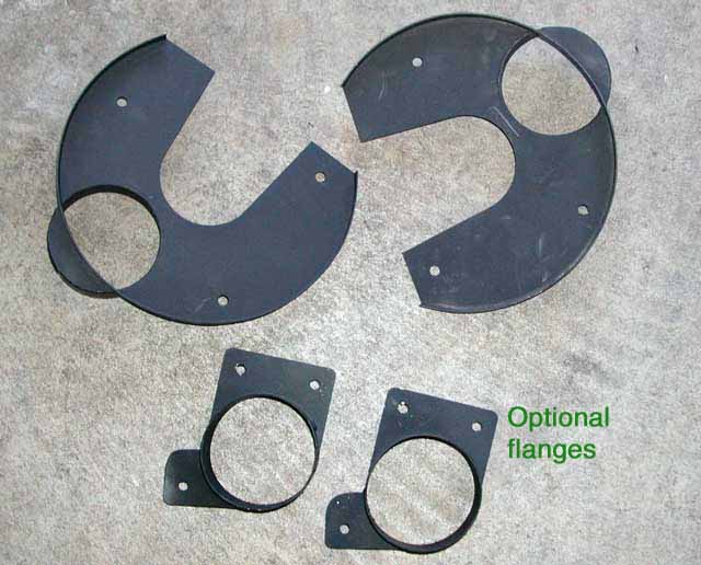
| P12. Backing plates and flanges |
|
| P13. Dust shield on the hub. The dust shield looks roughly like a hat with a wide brim. Remove the 3 attachment bolts. Arrow shows where to start working with a flat screwdriver to separate the flat "brim" part of the dustshield from the cylindrical part. The cylindrical collar will spin freely from the brim. Cut the brim section first at the narrowest point which marked by the arrow. Then cut the across collar section. |
|
| P14. Dust shield after cutting with tin snips. Arrow shows where the brim was cut. The cylindrical part of the dust shield is shown on the right. |
|
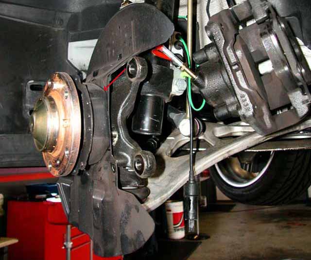
| P15. 2 views after installation of the backing plate to the 3 stock attachment points. A 3" bolt passes thru a 3" aluminum tube to connect to the top mounting point. You may have to grind 2-3 mm off the tube to prevent the rotor from rubbing the backing plate. A couple of washers can offset the 3" bolt enough to enable a firm fit; or you can cut the 3" bolt down by 2-3 mm. |
|
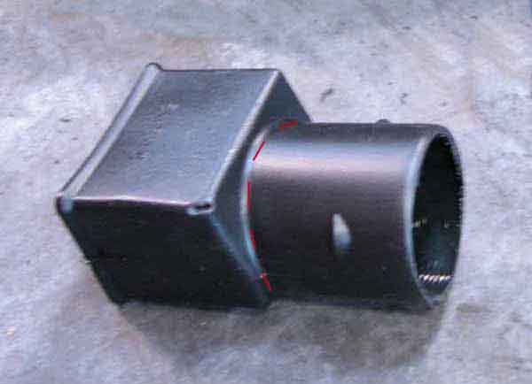
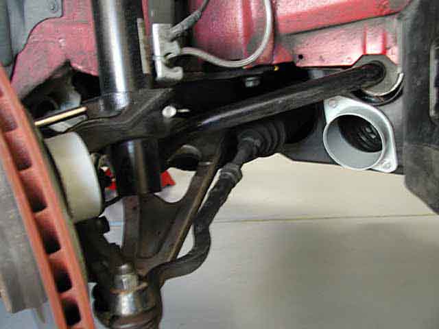
| P16. Connecting inboard hose to backing plate with connecting tube and outboard section of hose. The inboard hose can be joined to an outboard section of hose connected to the backing plate without the optional flanges. A 3" section of soft plastic tubing can be obtained from Home Depot or OrchardSupply Hardware. I used a rain gutter adapter that had a ~3" (actually 2.75") round section joined to a rectangular section- easily cut with a dremel tool or boxknife (see dashed red line in the bottom pix). 3" or 5" hose clamps were used to secure the hose sections to the tubing. (updated pix after installation of GC kit) |
|
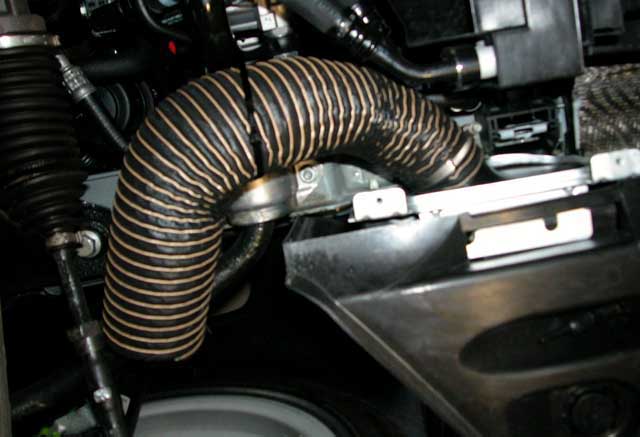
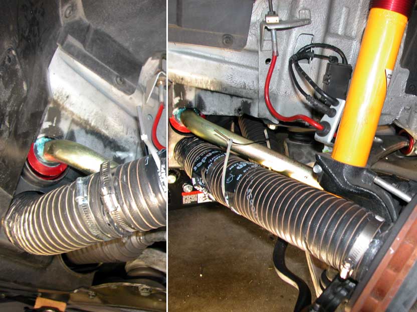
| P17. Connected hose sections. Left panel shows the joined hose sections using 3" hose clamps. Right panel: black tape over the hose clamps can be used to prevent chafing the sways. An optional tie-wrap was used to loosely secure the hose to the swaybar for extra security should a hose clamp work free. |
|
| P18. Completed cooling ducts-Side view. (old pix before GC) |
|

Fourth